
The principle of measuring the stress in thin films
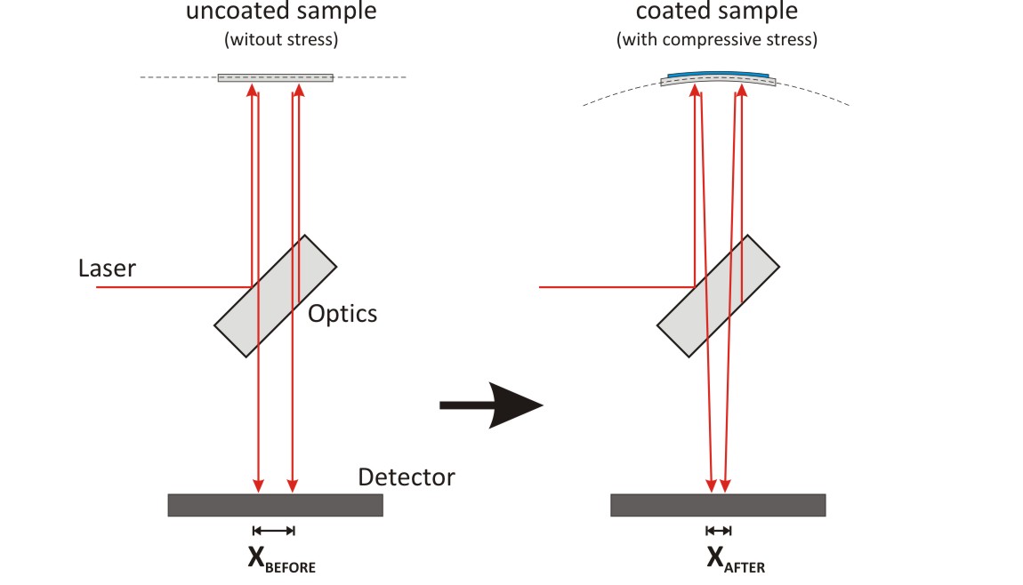
The above illustrations demonstrate the principle of all our stress measurement systems:
The beam of a laser is split into two parallel ones.
These beams are directed onto the sample. As one side of the
sample is (at least 3%) reflecting the beams they are redirected
back onto a detector where the actual distance of the beams is measured.
Before the coating the measured distance Xbefore equals the inital
laser beams distance after the splitting optic. After the coating
process, when the sample is covered with a stressed film(system),
the stress can lead to a bending of the sample. This occurs all
the more, as the sample is thinner. The laser beams are not
reflected parallel anymore. The measured distance of the
beams on the detector, Xafter, can then be smaller or
greater than the initial value.
By the following Stoney-formula the stress in the thin film
can be calculated by using the change in the measured laser beams distances.
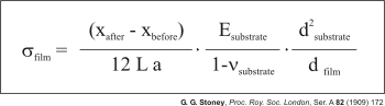
with:
| SIGMAfilm | Stress in the film |
| Esubstrate | Young's modulus of the substrate |
| vsubstrate | Poisson ratio of the substrate |
| dsubstrate | Thickness of the substrate |
| dfilm | Thickness of the film |
| L | Distance sample-detector |
| a | Distance of the laser beams on the sample |